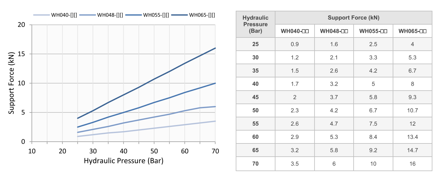
| Model No. | WH040 | WH048 | WH055 | WH065 | |||||||||||||
|---|---|---|---|---|---|---|---|---|---|---|---|---|---|---|---|---|---|
| Support Force at 70 Bar (kN) | 3.5 | 6 | 10 | 16 | |||||||||||||
| Lift Spring Force |
|
||||||||||||||||
| Plunger Stroke mm | 8 | 12 | 12 | 16 | |||||||||||||
| Cylinder Capacity |
|
||||||||||||||||
| Mass Kg | 0.65 | 1 | 1.4 | 2.35 | |||||||||||||
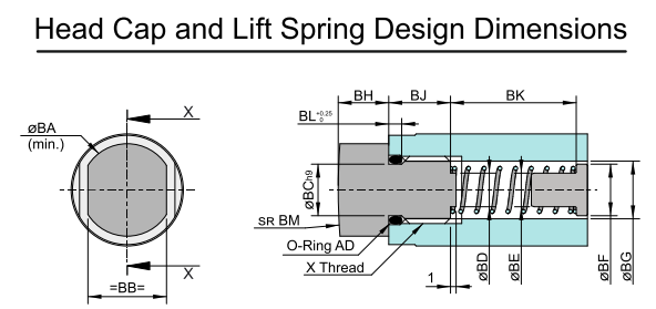
| Model No. | WH040 | WH048 | WH055 | WH065 |
|---|---|---|---|---|
| ØBA | 12.6 | 12.6 | 16.5 | 16.5 |
| BB | 11 | 11 | 14 | 14 |
| ØBC | 7.8 | 7.8 | 9.2 | 9.2 |
| ØBD | 5 | 5 | 6 | 6 |
| ØBE | 5 | 5 | 6 | 6 |
| ØBF | 7.2 | 7.2 | 9.2 | 9.2 |
| ØBG | 8.5 | 8.5 | 10.3 | 10.3 |
| BH | 7 | 7 | 7 | 9 |
| BJ | 9 | 9 | 11 | 11 |
| BK | 17.6 | 22 | 22.5 | 32.5 |
| BL | 2 | 2 | 2.3 | 2.3 |
| BM | 70 | 70 | 90 | 110 |
| X (Nominal X Pitch X Depth) | M10 X 1.5 X 12 | M10 X 1.5 X 12 | M10 X 1.5 X 13 | M10 X 1.5 X 13 |
| AD (O-ring – I.D X C/S) | 8 X 1.5 | 8 X 1.5 | 9 X 2 | 9 X 2 |
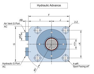
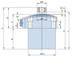
| Model No. | WH040F | WH048F | WH055F | WH065F |
|---|---|---|---|---|
| A | 68 | 79 | 82 | 102 |
| B | 30 | 41 | 42 | 57 |
| C | 26 | 26 | 28 | 30 |
| ØD | 40 | 48 | 55 | 65 |
| E | 11 | 11 | 11 | 11 |
| F | 54 | 61 | 69 | 81 |
| G | 45 | 51 | 60 | 70 |
| H | 56 | 67 | 70 | 87 |
| I | 31.5 | 35.5 | 39 | 46 |
| J | 22.5 | 25.5 | 30 | 35 |
| K | 34 | 40 | 47 | 55 |
| L | 61 | 72 | 75 | 93 |
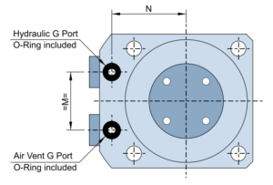
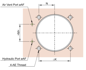
| M | 20 | 24 | 26 | 30 |
| N | 26 | 30 | 33.5 | 39.5 |
| O | 38 | 38 | 40 | 45 |
| P | 5 | 5 | 5 | 6 |
| Q | 4 | 4 | 4.5 | 5 |
| ØR | 9.5 | 9.5 | 11 | 11 |
| S | 15.4 | 14.5 | 14.5 | 14.5 |
| ØT | 5.5 | 5.5 | 6.8 | 6.8 |
| ØU | 15 | 16 | 20 | 22 |
| ØV | 73 | 83 | 90 | 104 |
| ØW | 14.5 | 15.5 | 19.5 | 21 |
| X (Nominal X Pitch X Depth) | M10 X 1.5 X 12 | M10 X 1.5 X 12 | M10 X 1.75 X 13 | M10 X 1.75 X 13 |
| Y | 13 | 13 | 17 | 19 |
| Z | 3 | 3 | 3 | 4 |
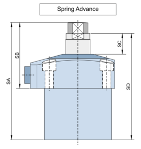
| SA | 76 | 91 | 94 | 118 |
| SB | 46 | 50 | 52 | 61 |
| SC | 13 | 17 | 17 | 22 |
| SD | 69 | 84 | 87 | 709 |
| ØAA | 14 | 14 | 14 | 14 |
| AB | 5 | 5 | 5 | 5 |
| AC | G1/8 | G1/8 | G1/8 | G1/8 |
| AE (Nominal X Pitch) | M5X0.8 | M5X0.8 | M6X1 | M6X1 |
| ØAF (MAX.) | 3 | 3 | 5 |